It's the off season: the perfect time for bike upgrades!

This year Nat has signed up for her first 70.3 triathlon so her TT bike will become the weapon of choice for training and racing with a long course focus. She is currently getting around on this Cannondale Slice Women's specific. It is the XS size with the 650c wheels which suits as Nat stands 156cm (5'2")

It was bought second hand and has served her well for a couple of seasons but it has fairly entry level specs:

  • 105 mechanical shift
  • Semi internal cabling
  • Basic aluminium cockpit
  • Conventional stem
  • Standard Tekro brakes
  • Ok 30mm deep aero wheels


So starts the project we will Blog about over the next month or so.


Sunday 26 July 2015

HANDLEBAR AND DIY Di2 REMOTE SHIFT - PART 2

After a few delivery hassles I finally received the Cateye #169-9200 buttons I needed to upgrade the handlebars and finish the project.  The buttons are impossible to get in Australia so I had them shipped from the U.S.

I have already progressed the DIY shift somewhat and this is discussed in a previous post.

My plan is as follows:
  • Start with the new carbon handlebars
  • Install the Cateye  #169-9200 buttons for shifting the rear derailleur
  • Install the R600 circuit board inside the stem
  • Internally wire between the buttons to the R600 circuit board
  • Wire from the R600 circuit board to the 5 port module on the stem
  • Reassemble with new brake cables
First I prepare the handlebars.  They are not designed what I have in mind so I need to drill a few holes.  I keep these holes around 3mm as I only intend to pull the very small 24AWG cables through them.  I don't need to feed any of the 5mm E-tube plugs through the bars.

Cables are fed from small holes in the back of the stem clamp area out to each bar end.  As with the main frame this was very tricky and I used old inner brakes cables as feeder wires.

A small hole is drilled on the inner side of each bar end 40mm from the end of the tube.  It needs to back from the end to clear the brake levers which insert in the tubes later.I fish the wires through and out of this hole.

At this stage I use a multimeter (or test light) to make sure the wires are still continuous and have not been damaged while I was pulling them through.

Next I add the buttons at each bar end.  There are a couple of ways to go about this:
  1. I could cut the Cateye cables and splice my wires onto them (Non-preferred)
  2. Connect my wires directly to the buttons (Preferred)
I use Option 2 because I don't like splicing wires and the buttons come with very flimsy wires.  Also the splice would end up inside the bars meaning I have to splice the cables before I pull them through the handlebars which is difficult and could damage the flimsy cables.

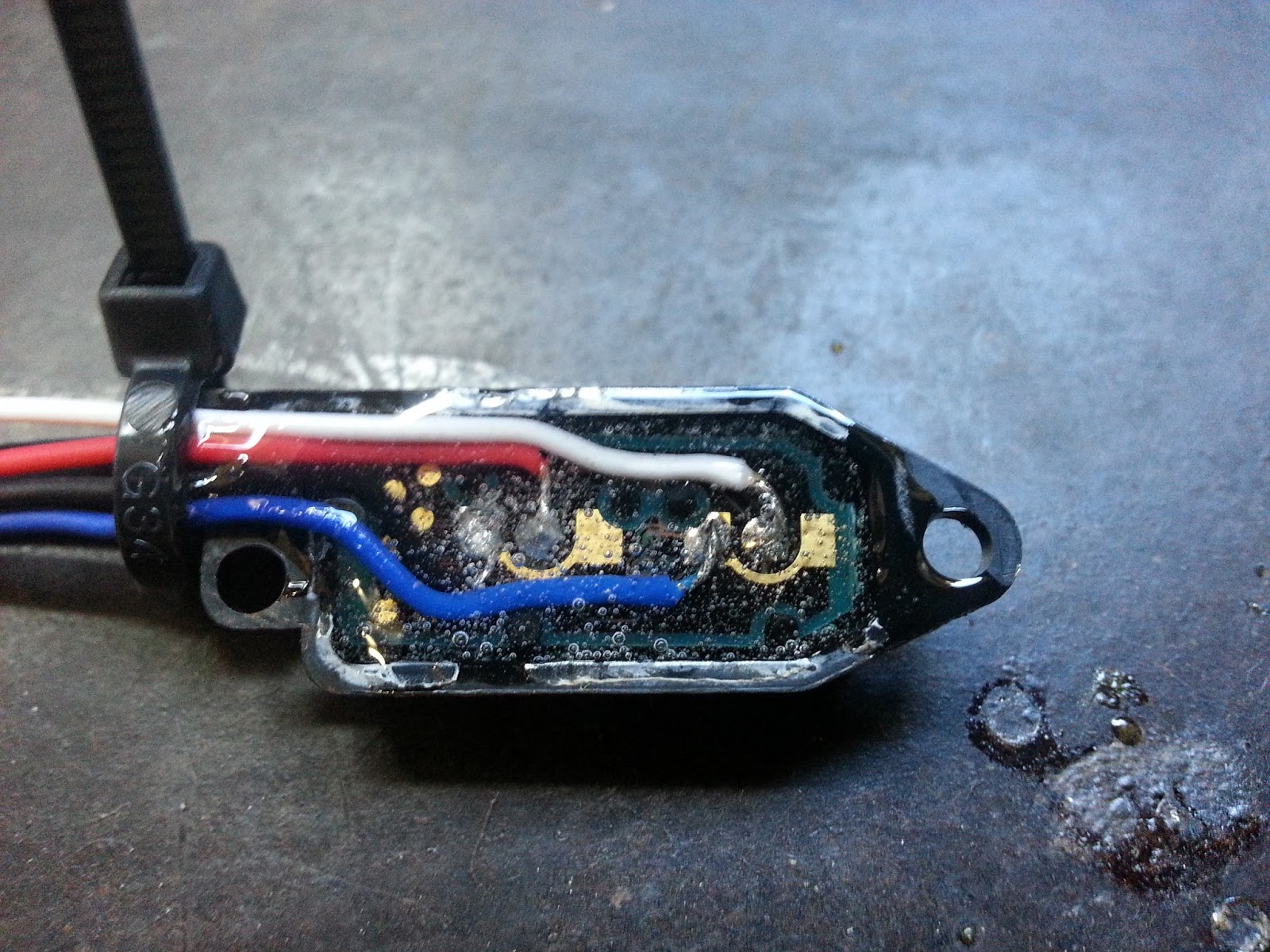
The picture below shows the buttons opened up which is very easy to do.  There was a small amount of sealant holding it together which I replaced with some 5 minute epoxy.  I de-solder the existing wires, pass my, more robust, wires through the button cover and solder them on to the same terminals:

I was on a roll and forgot to take pictures along the way but here is the end results with a button installed on the underside of the handlebars.

The button holders have some small cable guides moulded into them that clamp the cables and offer some strain relief.  Later the bar tape will wrap over and conceal these buttons.

Surprisingly when I did this on my Shiv upgrade a while back I found that even with thick winter gloves the buttons are every easy to use under the bar tape.

The other end of the cables at the stem get a set of the small red JST plugs to match those on the R600 module board and and I feed the brake cables through the designated holes under the bars and the whole assembly is now ready.

Next I move onto the stem and hiding the R600 rear derailleur control module.

I need to hide the R600 climbing module because it is just a control board removed from the shifter, is pretty ugly and no longer has a proper housing to mount it.  I decide to hide it in the stem but this means I need to drill a hole in the stem to get the E-tube wire out and around to the 5 port module on top of the stem.

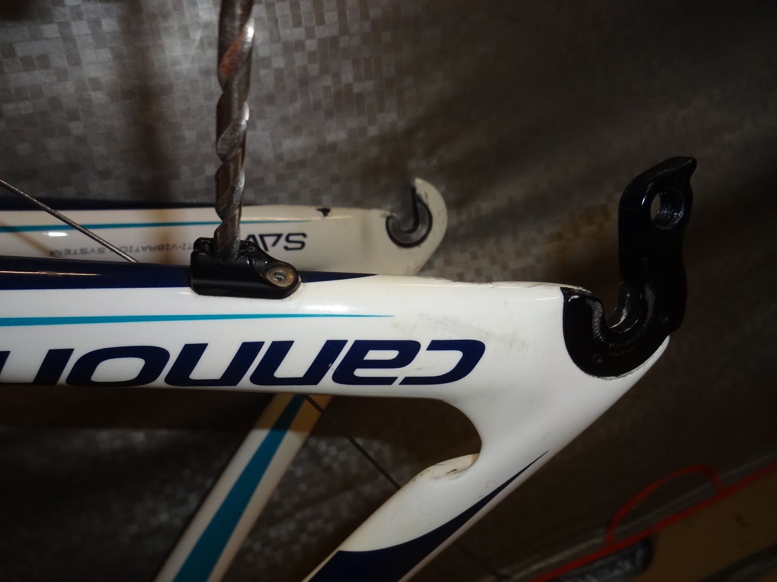
I am very careful about where I drill the stem as I don't want to weaken a high stress area.  A handlebar stem is a cantilever so when the rider puts weight on the bars the steam he top of the stem has the highest tensile stresses and the fork clamp area see the highest bending loads due to the lever action.


Image below shows the underside of the stem with the 5.5mm hole drilled on the underside and toward the handlebar end but not too close to the threads which may have local stresses from the bolt tensioning

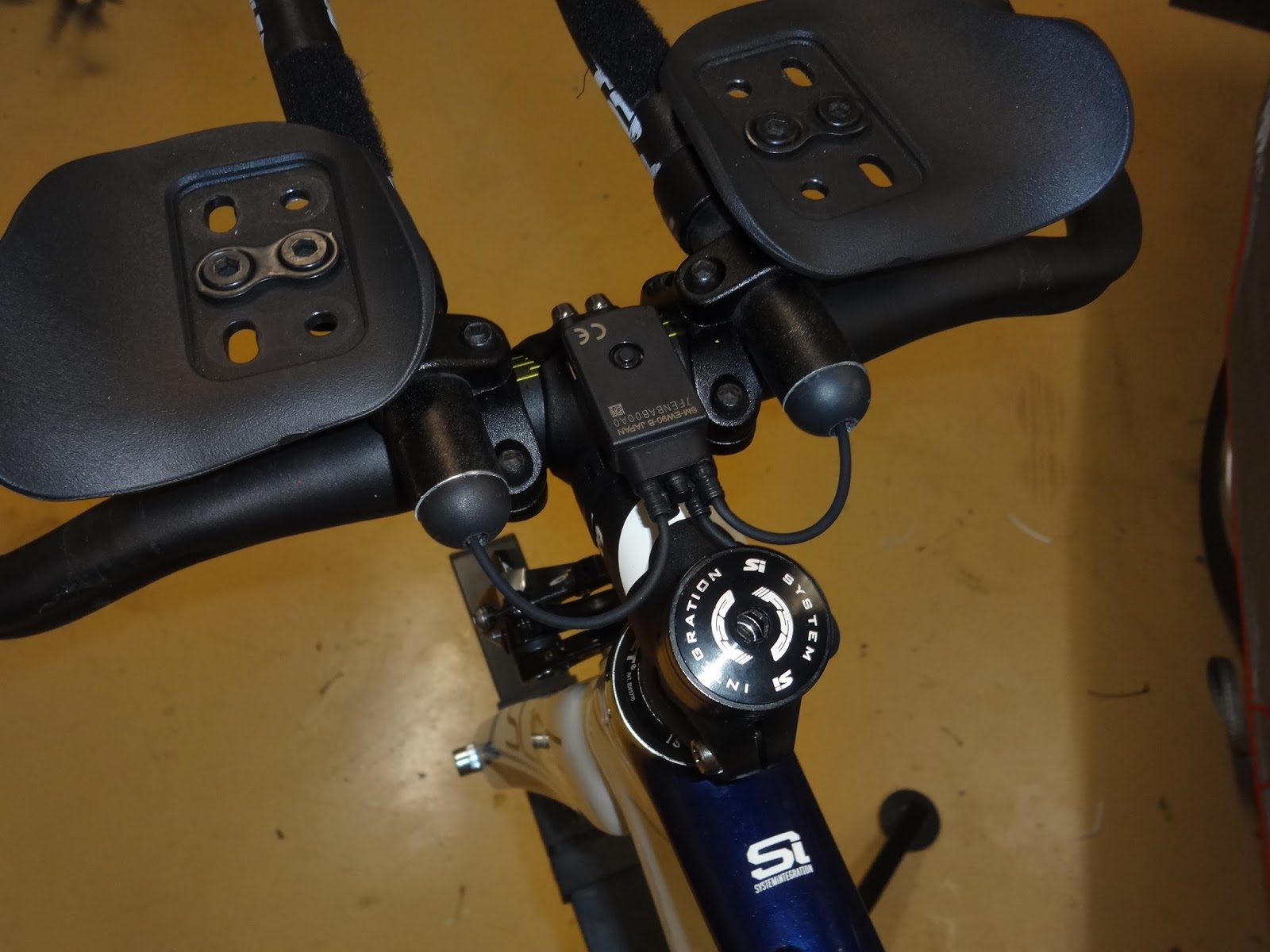
I route the E-tube wire from inside the stem up to the module on the top.  The module strap helps secure the cable to the stem.  The R600 module is wrapped with foam and zip ties which will stop it rattling inside the stem

The excess E-tube cable is wrapped around the module and it is all poked into the stem


Now the handlebars can be fitted and the internal wiring connected

From here it is just a matter of re-installing the aerobars, bar end shifters and the brake cables which I will write about soon.

Saturday 11 July 2015

Di2 AND BRAKE INSTALL - PART 2

I'm still waiting on the new cockpit and the front brake cable hanger so I decide to reassemble as so it can go back on the wind trainer for more trial bike fitting with the new stem and armpads flipped back to the top of the aerobars.

I cut the excess length off the base bar horns and now the only main difference is that the new base bar will be flat and sit 35mm higher than the drop bars on there now.  Pad height will be similar.

Refit the old cockpit and shortened base bar


TRP T920 Front brake installed ready for cables

A-Junction installed on top of stem (stem was too short to mount underneath)


Re-fit old bar tape until and reuse the old rear brake cable until the new bars arrive

Back together on the ZIPP wheels (Stealth look until decals arrive)

Training wheels and XLAB pocket 100 Bento box which fits in perfectly behind the stem.

Tip - Bento box is a great spot for the TV remote while on the wind trainer!

Really happy with the results so far, no more lever style bar end shifters, just crisp reliable shifting at the push of a button and a much cleaner looking ride!

We are still waiting on, Carbon Cockpit, Front Brake Hanger, Cateye Buttons and Zipp decals which should arrive in the next week or so.

We will have a few finishing touches before it is fully race ready, such as installing some drink holders and fine tuning the bike fit.

Di2 DIY TIME TRIAL REMOTE SHIFTERS - PART 1

One of the great parts about electronic shifting is the ability to install multiple shifters.  In this case we want shifters at TT bars and the brake levers on the base bar.  While this is great, it is also quite costly with the Shimano Di2 Brake levers retailing at around $400 with no other alternatives on the market right now.

This do it yourself time trial remote shifter mod is nothing new, quite a few people have done this for bikes where replacing the brakes levers isn't possible, e.g hydraulic brake levers and my Shiv TT where I need the cable adjusters barrels in the brake lever.

This modification requires the following parts:
  • SW-R600 Climbing shifter (Options are SW-R671 or ST-6770/6870 right shifter)
  • 4 x 0.5m lengths of small electrical cable (I stripped a 4 core alarm cable 24AWG)
  • 2 x 2 pin connectors (I used JST connectors used for RC cars)
  • Cateye #169-9200 Remote Buttons
  • 5 Minute Epoxy
  • Heat Shrink
  • Soldering Iron
Note these parts will provide control for the rear derailleur only.  I will install one button at each brake lever.  The left button for an easier gear, right button a harder gear.

If you want to install front derailleur shifting also, you will also need an STI or time trial left side shifter and some extra buttons.

I unscrew and disassemble the shifter body

Remove the main circuit board and dispose of the rest

I remove the cover and buttons from the circuit board


The circuit board is now ready for the remote button wiring

I Solder the 20AWG wires to the button contacts as shown below.  I stagger the wires to ensure the centre wires don't cross the outer contacts or the other wires where they could short out.

Shifting occurs when White & blue or Red & Black are connected via a remote push button.

At this stage I plug the E-tube wire into the module on my bike and test the shifting by touching the wire pairs together momentarily.  If it tests ok I seal up the unit with 5 minute epoxy.

I add some small JST connectors and heat shrink.  I use the male connector on one pair, female on the other to prevent potential mix ups when I assemble it later.

I have the remaining lengths of 20AWG cable with the terminals crimped and ready to go waiting for a set of Cateye #169-9200 remote buttons and the new base bar to arrive.

Wednesday 8 July 2015

Di2 INSTALLATION PART 1 - INTERNAL CABLES AND BATTERY

The Di2 components have arrived so now the fun begins!  I will let the pictures do the talking now that the planning is out of the way and I’m getting my hands dirty.

NEW PARTS HAVE ARRIVED
First I strip the bike down to a bare frame and fork.  I fit the new stem to stop the fork sliding out and to allow me to locate the A-module later and finalise the front wire location.

PREPARE FRAME FOR INTERNAL CABLING

I still need to do a bit more preparation for the internal cabling

As shown in a previous post I had already drilled a 7mm hole to provide cable access from the seat tube to the bottom bracket cavity.


To prepare for the rear derailleur cable I remove the mechanical cable stopper from the underside of the drive side rear stay.
DRILL RIVETS OUT OF CABLE STOP
PRY CABLE STOP AWAY FROM FRAME
 I enlarge one of the holes to 5.5mm enough to feed the 5mm head of the SD50 cable through.
ENLARGE ON RIVET HOLE TO 5.5mm

To prepare for the front derailleur cable I first remove the old plastic cable guide
REMOVE THE OLD CABLE GUIDE
Drill a 5.5mm hole to allow the cable to pass from the bottom of the existing cable guide into the bottom bracket cavity as shown.
DRILL INTO BOTTOM BRACKET CAVITY
I could pass that cable outside of the frame this is neater and keeps the B junction more securely inside the frame.  The small guide tube that was drilled was very thin and not structural.

The existing downtube cable entry had an aluminium cable stopper which only allows the inner cable to pass into the frame.  I used the 5.5mm drill again to ream the insert all the way through so the SD50 Di2 plug could pass into the downtube.
DOWNTUBE CABLE ENTRY
INSTALL INTERNAL CABLES
Once the frame is prepared the internal cables can be installed.  I used old shifter cables to feed through as trace wires and then attached the trace wire to the SD50 Di2 Cables with tape and draw them through.
A few tips for drawing the cables through:
  • Masking tape holds better than electrical tape
  • Tape the trace wire in line with the plug so it fits through the 5.5mm holes
  • Only wrap tape once around the 5mm plug, any more will get stuck in the 5.5mm holes
  • Wrap plenty of tape on the trace wire to get a good grip on it
  • Plug cables it into the B junction straight away while you work on the others
  • Make sure you have the proper Di2 plug tool
Get all the cables through and connected at the B Junction
REAR DERAILLEUR CABLE
BATTERY CABLE
A-JUNCTION CABLE
B-JUNCTION AND FRONT DERAILLEUR CABLE

I fit up the derailleurs and A junction and plug them in then push any excess cable length back into the frame and slide the B Junction inside the bottom bracket cavity.

I allow some length for the rear derailleur cable to move across all 10 gears and check that the fork can turn through full range without pulling on the cables.

Finally use the Shimano SM-EWC2 cable tape to secure the cables to the frame around the front derailleur and stem.  This keeps them out of the way and reduces the risk of damage.

SECURE CABLE NEAR HEADTUBE
SECURE CABLES NEAR FRONT DERAILLEUR

INSTALL INTERNAL BATTERY
The Battery needs to go in the seat tube and there are a few options.  Most Di2 specific bikes have a grommet and clip retainer available to secure the battery in the seat tube.  I couldn’t find such a thing so I am going to use a flexible Polyurethane adhesive to bond the battery in place.

READY TO BOND BATTERY INSIDE SEAT POST
I spread the adhesive on both sides of the battery, inserted it against the front side of the seat tube with slight pressure to spread the Sika.  I then used a pop stick and hacksaw blade to smooth out the back side and form a fillet join between the battery and either side of the seat tube.
ADD TWO BEADS OF ADHESIVE TO THE BATTERY
INSERT BATTERY AND SMOOTH OUT ADHESIVE


I used is Sikaflex 227 which I is used by coachbuilders for fibreglass panels.  It is flexible, dampens vibration, won’t harm the epoxy resin.  It can be sliced with a utility knife and prised or scraped loose to remove the battery.

The result is very secure.  I installed my SHIV TT battery two years ago and have ridden 10,000km with no hassles.


Monday 6 July 2015

BRAKE UPGRADE

The only aspect of the bike that has not yet subject to technical scrutiny was the brakes.
During our review of the current mid-range women’s time trial bikes we noticed most of them still compromised with conventional road bike callipers and cables in front of the forks tarnishing the clean lines of the sleek carbon framesets.  We were really hoping to find something with an integrated front end and hidden brakes, a feature of many  many modern triathlon superbikes that pushes them into the higher price bracket.

When we made the decision to re-use and upgrade the Cannondale Slice frameset the standard brakes  was one area of compromise we thought we'd have to accept.  The existing Tektro centre mount dual pivot callipers had ample stopping power and we figured they would get a service and be retained.

While gathering ideas for the project we often referred back to the Felt B2, our preferred option in this years range and we evenetually noticed something different about the front brakes!  They were still front mounted but a much sleeker centre pull design.


A bit more reading revealed that Specialized  used a similar setup their Transition & UCI legal Shiv TT bikes.

The simple stem mounted cable hanger was also available from TRP and I could see how this could be adapted to work on our Slice.

So a front brake upgrade was added to the list of upgrades and as usual I start with a criteria list:

FRONT BRAKES CRITERIA
U-Brake Style Symmetrical Callipers
Centre Fork Mount (U Brake Adapter)
Centre Pull Actuation
Stem Mount Cable Hanger
45mm reach (See note below)
Sleek and Aero Design
Improve Visual Impact


After some enquiries with Tektro and TRP I learned that the Centre mount, centre pull, U-Brake were OEM only and not available aftermarket!
  • Felt B2 - Tektro T726R  - OEM only, and not very aero
  • Specialized - TRP T920 - Very aero but twin mount only
I could get a centre mount, side pull or dual mount centre pull which would not fit my centre mount limitation. So the only solution was to buy a few different sets to mix and match the parts which was going to double the cost.  The parts I wanted needed were:

TRP T925R
U-Brake single bolt
31mm-49mm reach
TRP T920 
Symmetrical Aero arms
Centre pull linkage 


I found one  second hand (unused) and the other directly from TRP for a total price I was happy with so I took a gamble and ordered the parts along with the TRP cable hanger.

At this stage I am not sure that the T920 Arms will actually fit the pivots on the T925R adapter bracket or whether the combined assembly will align nicely on the front of the bike but I think it is worth a try.  My Shiv TT already has very similar brakes on it so I am confident they will provide adequate stopping power.

I eventually discovered that Tekro actually sell a U-Brake adapter separately as shown (Right).

NOTE: I required a 45mm pad reach.  This is the distance from the caliper mounting bolt down to the Rim braking surface.  I chose the TRP T925R designed for 39mm-51mm Pad reach.  The T925FR version had an offset adapter and a 55mm-67mm pad reach designed for installation behind the front forks.